Restraint (Bracing) Overview
Introduction
There are several reasons for truss bracing in a roof or floor structure. During construction, before all of the components of a truss system are in place, bracing acts to hold members upright, straight, and in place. This “temporary restraint” typically may not be the responsibility of the structural engineer. However, contractor clients may hire the engineer or component manufacturer to design this temporary bracing, since it can be very costly and dangerous if improperly addressed.
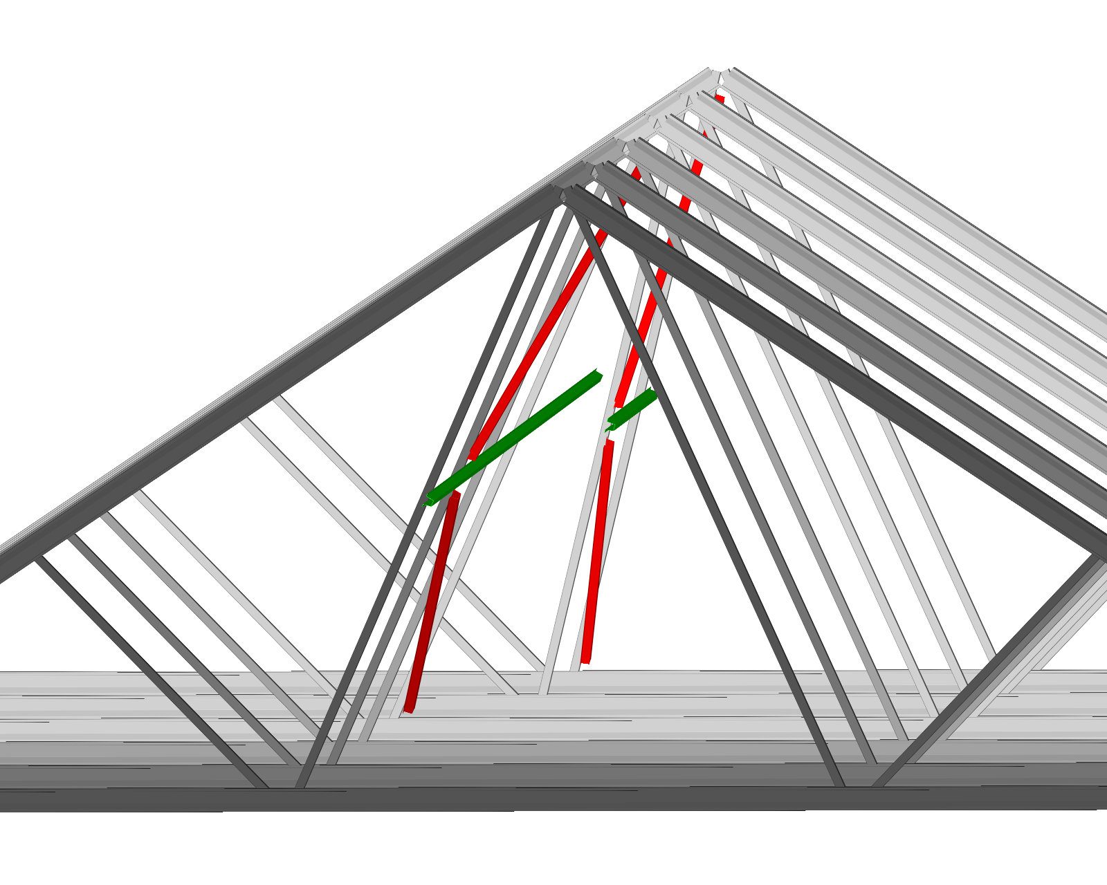
Truss restraint also acts to transfer loads to other parts of the structure that can better resist these loads. Often, a single truss or truss member cannot take certain loads by itself. Specific types of restraint can often help redistribute the load over multiple trusses or to stiffer supports if needed. For individual truss members, if the axial load is too high for a given slenderness, weak axis bracing can reduce the effective length and increase member capacity.
Bottom chord restraint, even in conditions where the bottom chord remains in tension, can help insure web member capacity is as the designer expected. If the bottom chord is left unrestrained, axial compression in web members can produce a horizontal force at the bottom chord, especially with back-to-back (offset) web members. If this force is not restrained, the effective K value for the compression web could be considered to be as much as 2, which may greatly reduce the load carrying capacity of the member. Bottom chord restraint is also required where wind uplift loads create bottom chord axial compression. Although compression may not be the governing load condition, even small amounts of axial compression can result in failure of long, unrestrained members. A good rule of thumb is to follow the restraint requirements found in the CFSBCSI: Guide to good Practice for Handling, Installing, Restraining & Bracing of Cold-Formed Steel Trusses or to restrain the truss chords at each panel point.
Temporary Restraint
Temporary Restraint is covered in the CFSBCSI: Guide to good Practice for Handling, Installing, Restraining & Bracing of Cold-Formed Steel Trusses. It is the restraint placed in the trusses at the time of truss erection. Temporary restraint is often kept in the structure and allowed to double as permanent restraint. It may also be used to facilitate truss installation by reinforcing them against the different stresses induced during lifting or staging. Often, several trusses or even an entire section of roof or floor may be connected together and lifted in place.
Temporary restraint may be used to help accomplish successful lifts. The CFSBCSI: Guide to good Practice for Handling, Installing, Restraining & Bracing of Cold-Formed Steel Trusses also gives some guidance on temporary restraint configuration and location. CFSB2 – Setting Trusses & Installation Restraint/Bracing
Permanent Restraint
Permanent Restraint is covered in CFSBCSI: Guide to good Practice for Handling, Installing, Restraining & Bracing of Cold-Formed Steel Trusses. This is restraint that is required to stay in the truss system for the life of the structure. Permanent restraint helps resist the long and short-term loading and load combinations specified in the building codes. Proper attention to the permanent restraint design will insure the structure will meet the demands placed upon it during its service life. See also CFSB3: Permanent Restraint/Bracing of Chords and Web Members.
Sheathing is an important component of the roof truss permanent restraint system and must be designed to resist loads. It is typically attached directly to the top of the top chord members and is sometimes used as part of the roof or floor diaphragm. Sheathing restrains the members that it is attached to and helps distribute the restraint loads out to the building elements that resist lateral loads. Sheathing is the most efficient way to distribute these restraining forces.
Occasionally, sheathing is not attached directly to the truss members. Often, “Z” or “F” (furring) members are used where sheathing cannot span the distance between trusses. These furring members may be designed as restraint members. The designer must include both the bending loads induced by the sheathing, as well as the axial loads from the member restraint force.
With piggyback trusses or overbuilt trusses or rafters, some portions of the top chord are not immediately adjacent to the roof deck or sheathing. Nonetheless, these chord members may experience high axial loads. The designer must ensure that sheathing, furring, or other members are used to restrain truss chords below piggyback trusses and below overbuilt rafters, or design their top chords with longer unrestrained lengths in these areas. CFSB3 Summary Sheet – Permanent Restraint/Bracing of Chords & Web Members
Restraint Methods
Entire manuals and chapters have been written on truss system restraint; here is an overview of some of the truss restraint options available to the designer.CFSBCSI: Guide to good Practice for Handling, Installing, Restraining & Bracing of Cold-Formed Steel Trusses provides additional guidance, equations, and a method for designing system restraint. This overview includes those factors that need to be taken into consideration.
Lateral Restraint
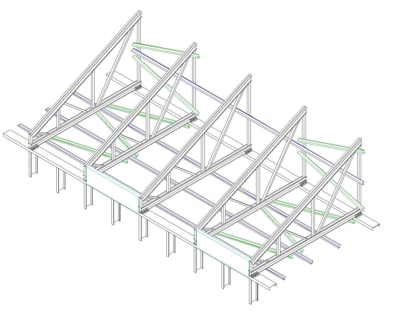
Lateral Restraint are restraints between chords or webs of adjacent trusses. These are typically placed perpendicular to the plane of the chord or web, and with C-shaped, angle, or tube shaped web members, they can be attached directly to the flanges of adjacent truss members. Lining up the truss webs can make the restraint installer’s job much easier.
Diagonal Restraints
Diagonal Restraints are restraints placed between lateral restraints, in the same plane, and between chords and webs of trusses. Diagonal restraints may also be termed as X-restraints or cross restraints, because of their appearance within the structure. As seen in plan, diagonal restraints used at the chord plane act as a sort of “flat truss”, transferring loads from the lateral restraint to adjacent walls or adjacent drag struts. Individual chords of adjacent trusses may become a part of this diagonal restraint flat truss system. If this is the case, these trusses must be designed for the added restraint loads, as well as the typical load combinations from applied loads. Diagonal restraint used at the web plane act as sort of a chevron restraint for the truss system and transfer loads from the web lateral restraint to the roof deck and bottom chord plane.
Bridging
Bridging is a restraint between the top chord of one truss to the bottom chord of an adjacent truss. Bridging may also extend from a location of web restraint to a roof or ceiling diaphragm.
Blocking
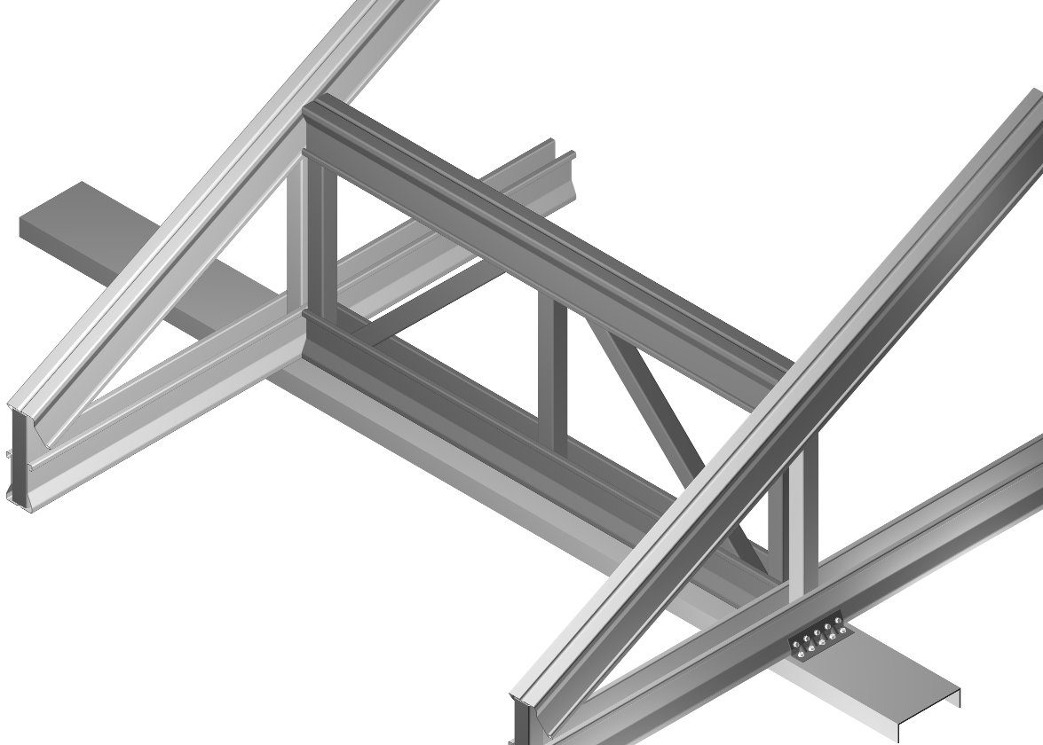 Blocking may be part of the truss restraint system, but it is more likely to be used to transfer lateral diaphragm loads from the sheathing or roof deck down to the shear wall or drag strut below. Blocking may be accomplished using diagonal straps, a brake metal shape, or an actual truss to transfer these loads.
Sway restraints
Sway restraints are bridging restraints installed to avoid truss tipping. These are typically used as temporary construction restraints.
Design of the individual restraints can be daunting and complex, but the use of some simple guidelines can greatly ease the task. “The design should be performed using a minimum of 2 percent of the full member axial forces. There are various other sources that give guidelines and data for restraint force design. It is the responsibility of the designer to determine which source to use and what assumptions are made about rigidity of supports and of the system.
Restraint Design Responsibilities
A question that is still hotly debated is, “Who designs the restraint, and who is ultimately responsible?” As the building designer, the architect or engineer of record is responsible to see that the restraint is designed and installed properly. However, the appendix to the AISI truss design guide and AISI’s Standard for Cold-Formed Steel Framing – Truss Design spell out at least part of the responsibilities of the owner, building designer, and truss designer. All of the above references specify that the building designer is responsible for the permanent truss restraint, and that the truss designer is responsible for defining the locations of required permanent truss member restraint.
Some engineers (building designers) will include statements in their specifications that spell out restraint design responsibilities. Contractors and truss designers bidding on these documents must carefully read these requirements, to ensure that everyone is clear about who does what before bids are issued. The wording of the structural general notes, as well as the specifications, must be consistent and clear on restraint issues. Although it is the responsibility of the specialty engineer to ensure that the truss elements will not fail, ultimately it is still the building designer’s responsibility to review the design and ensure it is compatible with the other elements of the structure.
Get Help with Restraint Design
Restraint of trusses and truss systems can be complex, and is often ignored by design professionals. Many engineers rely on component manufacturers to give guidance on restraint of truss systems. The Cold-Formed Steel Engineers Institute, the Structural Building Components Assocoation – Cold-Formed Steel Council and the American Iron and Steel Institute (AISI) have excellent resources available that give general guidelines. However, the engineer of record is ultimately responsible for the design of the structure, and therefore needs to confirm that the truss system restraint design has been adequately addressed.
TrusSteel offers extensive engineering services through our affiliation with a strategic partner BBD Engineering & Design Firm (www.bbdengineering.com), a fee-based, full-service consulting engineering firm. The local TrusSteel fabricator can provide drawings that illustrate how and where it is allowable to connect restraint and other framing to TrusSteel trusses.
Industry References & Guides
American Iron and Steel Institute (AISI) – www.steel.org
The Cold-Formed Steel Engineers Institute – www.cfsei.org
Structural Building Component Association, Cold-Formed Steel Council – sbcacomponents.com
North American Standard for Cold-Formed Steel – Structural Framing, 2020 Edition (AISI S240-20)
CFSB1 – Guide for Handling, Installing, Restraining & Bracing Trusses
CFSB2 – Truss Installation and Temporary Restraint/Bracing
CFSB3 – Permanent Restraint/Bracing of Chords & Web Members
CFSB4 – Construction Loading
CFSB5 – Truss Damage, Jobsite Modifications & Installation Errors
CFSB11 – Fall Protection & Trusses
Cold-Formed Steel Truss Jobsite Package